
printing-parts from a prusa
29. März 2013
hey guys,
some people say its not possible to print high quality parts with diy printers. I see this a bit different.
It just depends on the time and effort you put in your machine.
Here are some printed parts from thingiverse which my wonderful girlfriend painted.
They are all printed on a prusa, with white china PLA in 3mm diameter.


Workshop
17. Dezember 2012


Ramps 1.33 by geeksbase.com
18. November 2012
Geeksbase Ramps PCB V1.3
This is our new complete electric for the reprap printers on one PCB. Base is the arduino mega!
We changed some things to make a better reprap-pcb.

advantages:
The PCB can manage two extruders!
All traces are bigger to provide a better current flow!
On the whole pcb we designed a “hatch”. The effect of the hatch is that the whole PCB works as a cooling element! So all generated heat discharge perfect and the operating temperature stays in a perfect range.


All screwed contacts where replaced against male/female connectors.
So you could change the whole electric and single parts really fast. We dont use many SMD-parts. So the stepperdrivers are replaceable. We only deliver the Pololu A4988, which has a automatic overheat-automatic
With the Arduino Mega as base its possible to build reams of addons. (like display, keyfield, etc.)

Geeksbase Hotend assembly
3. November 2012
Today how to assemble our Hotend in V1.0.
First you need all parts of the Hotend:
+nozzle
+heatblock
+adapter
+peek-isolator
+2x copper-washers

 Although you need some wenches and a roll of Teflon-tape.
To screw everything tight together use the wenches. The teflon works like a seal.
 First you have to put the cooper washers on the threads, next wind the Teflon-tape around them.

Screw everything loose together. Then take the wenches to screw everything tight.

Be careful and remember after tight comes loose.

Now take a bench vice. Put some filament into the peek-isolator to avoid squeezing the isolator together! Although take a piece of paper to make sure that the isolator don’t gets damaged.


Now where everything is fixed you need the heat-resistor and the temperature sensor.
I isolate both with kapton. So i could be sure tthat there is no short in the circuit.
 With the temperature-sensor its a bit hard to isolate him. But with some to time you get it.
Otherwise it will not show the right temperature.
 Now take a small roll of kapton and warp it around the heat-block. Make sure that the heat resistor and temperature-sensor sits right in position.
 Now take some heat-paste and fill of all space with air. Its important so you could be sure. That the temperature-sensor reads the right temperature and the heat resistor works for a long time.
Ready for use. Some tips for starting the hotend for the first time, i will give you in a few days!

Workshop on the 02.11.2012 to 04.11.2012
14. Oktober 2012
DER WORKSHOP FÄLLT AUS! (die restlichen Teilnehmer wurden von mir per Email informiert)
Ein neuer Workshoptermin für den Hackerspace wird in den nächsten Tagen bekannt gegeben!
—————————————————————————————————————–
We plan to do a workshop in the 02.11.2012 to the 04.11.2012. For more Informations contact us: info@geeksbase.com

be aware … something new
19. August 2012

heatbed assembling
13. März 2012
Today how to assemble the MK2 Heatbed-Plate(HBP): First solder the SMD-Parts on the plate. We used:
- 2x SMD-805 leds with blue color
- 1x SMD-805 resistor 490 ohm

If you solder by hand, be quick. SMD-parts dont like to get heated up to much. After soldering the parts on, take two cables with different color. Black and red for example and make sure that the cable has a cross-section (thickness) of min. 0,75mm². Attention please! The HBP takes up to 12A and thin cable will meld in short time.
Great after soldering all parts and cables on we will take a heat thermistor which detectes the temperature of the HBP. Beside you need a roll of kapton to isolate everything. A cuttingknife. Heatthermistor and a short cable 0,15mm² for example.


On the right picture you could see that the heatthermistor-legs arent long enough to reach the outside of the plate. We will cut of the 0.15mm² cable to get some thin cables and make the thermistorlegs a bit longer.


Left: How to get a small thin cable out of a bigger one. Right: the thermistor with longer legs. After isloate each leg of the thermistor, mount a isolated cable on the outside of the bed. This guarantee that you have a really flat surface.

Now I tape some kapton around all cables. I love kapton. Its sticks really well, is perfect for electric components, temperature resistent and easy to remove. So if anything broke i can fix it fast.
Now lets come to wire up the heatbed to the printer-electric. After a lot of testing. Smoking boards and messauring temperature over hours, we decide that there are two options how you can power up the heatbed.
Any other options we tested are NOT MADE FOR CONTINUOUS or SAVE use!! (be aware this is DIY)
First solution (using a SSD-Relay – best choice):
Things you need:
SSD-Relay – Input 3-32VDC – Output 24-240VAC up to 20A(will work with 12V)
ATX-powersupply – min. 12v up 12A
some thick cables (1mm² – bigger is better)


Lets start with the ATX powersupply. In general its wired up to a computer and if you press the ON button of your computer. The powersupply starts. We have no computer so we make a little trick.
We have to bridge the contacts that are responsible for the startup of the ATX powersupply. Use the contacts 04 and 05 and bridge them with a cable.
Now the ATX powersupply will start immediately.


Next we need some open cables from the supply to wire them up with the heatbed. Search for a 4pin connector. Most times black and yellow.
Normally it goes to the CPU of your motherboard.
So you there must be enough power to heat up the heatbed.
Cut of the 4pin connector, we need to of the cables.. The others can be isolated or used to power up the printer-electric.
(i prefere to use 2x powersupplys. 1x for the printerelectric and 1x for the heatbed – seperate big electric components is used in the industry to avoid faults )
Now take the two cables from the power supply and the two of the HBP supply and mount them on the SSD-Relay.
1 – 12v+ Powersupply
2 – HBP (one cable)
the two other cables, ground of the powersupply and the HBP cable no.2 have to connected together. So solder and isolate them for example or use a connector.

Now we have to connect the SSD RELAY input with the ramps heatbed-output.
(Cool the SSD-relay with a fan, it will heat up!)
Make sure everything is wired correct.Test it!
Secound solution (using a BIG MOSFET on your electric – a bit more advanced):
coming up soon….
IMORTANT NOTICE:
All components of a selfbuild heatbed have to been choosen right.
Use thick cables! Cool down all switches (SSD or Mostfet) because they getting hot while driving so much energy.
Use it carefull to have fun with printing.
geeks:base mendel build log
18. Februar 2012
Today we build a mendel. And after many questions, we think about writing a small blogpost with pics and tips for building the printer.
This is a small instruction how you could build it.
First a list of all parts you could use to build a mendel classic.
Lets start with a overview. So it will be much easier to talk about all single parts:

We will start with all single-parts.
Because its better to have build them first together. Otherwise you could get in trouble if you build the ground-body and miss to build in some single parts.
Belive me i build a few mendels, and unscrewing is not the biggest fun on such projects ![]()
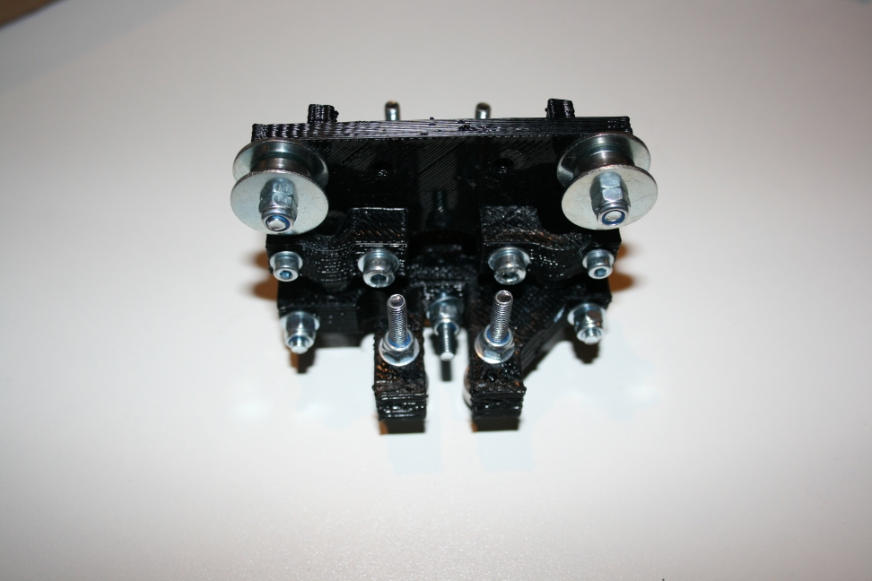
We will start with the x-axis motor-holder:
N°1 – X-Axis motorholder


You need:
4x 624er bearings
4x M4x20 screws
8x M4-Washer (big ones)
12x M4-Washer (standart)
4x M4-nylon nut
Build the 4x bearings with this parts together. Right beside the bearing on each side you have to place 1time a small washer and then a big washer. So the bearings run smooth and the rims are save in position.
To mount the motor and the small brakets to clamp the smooth-rods use 8x M3x20.
You need 4x Washers for the screws of the motor.
For the brakets on the outside you need washers on both sides and 4times M3-nuts (nylon-nut).
N°2 – X-Axis counterpart

For the X-Axis counterpart you need this parts:
For the bearings X-Axis (rim):
2x 624er bearing
2x M4x20
6x M4 Washer (standart)
4x M4 Washer (big ones)
2x M4 Nuts (nylon nut)
For the small brackets you could use:
2x M3x 20 Screws
2x M3 Nuts-normal
4x M3 Washers
2x M4X20 Screws
2x M4 Nuts (nylon nuc)
4x M4 Washer (normal)
For the bearings (z-rod):
8x M4x40 Screw
16x M4 Washer
8x M4 Nylon-Nut
N°6 – Z-Clamp-part(motorside)


Parts you need:
4x M4x20 Screw
4x M4x35 Screw
10x M4x40 Screw
36x M4 Washer
18x M4 Nylon-Nut
1x M8 – Nut
6x 624er Bearing
N°5 – Z-Clamp-part(counterside)


You need:
4x M4x 40 Screw
4x M4x 35 Screw
16x M4xWasher
8x M4 Nut (nylon)
1x M8 Screw
N°7 – X-Sliding carrier


10x 624er bearing
6x M4x40 Screw
10x M4x20 Screw
16x M4 Nut (nylon)
16x M4 Washer (standart)
Oozing and Retraction
26. Januar 2012
after some little talks with stoffel i’ve thought about,whats the best way to retract.
whats the actual problem with retract?
the retraction distance is konstant, so we retract these constan even if we have a traveldistance of 5mm or 5m (yes i know 5m are big, but its only to show the problem).
what the most people see what happens on retraction:
1. print normaly
2. retract
3. drive any distance with the extruder
4. re-retract
5. print normaly
what most people see what happens if retraction is not used:
1. print normaly
2. drive any distance with the extruder
3. string happens
4. print normaly
what realy happens on retraction:
1. print normaly
2. retract
3. drive any distance with the extruder, filament in nozzle is heating up constantly
4. re-retract
5. blob happens
6. print normaly
what realy happens without retraction:
1. print normaly
3. drive any distance with the extruder, filament in nozzle is heating up constantly
5. string happens
6. print normaly
thats the reason, why short heating zones doesnt ooze so much.
problem with short heating zones: you cant print fast, because you cant heat up the filament fast enougth.
another little problem, but its irrelevant, because its a very little constant: the heated up filament will blow up a little bit if the pressure is removed.
easy solution:
skeinforge: set a negative retraction restart extra distance.(dimension)
slic3r: set a negative Extra length on restart.(Print settings -> retraction)
but this will just help a little bit and on short distances! If your restart extra distance is to high, your nozzle isnt filled with material and a gap will happen.
better solution:
retract linear relativ to the driven distance. on little distances much better than the standart konstant retraction. doesnt work on great distances!
best solution:
retract logarythmic to the time that the printer need to change its position.
this solution will bring some benefits: no blobs, no strings, no ooze, no re-retraction needed.
and its irrelevant how long you travel ( not realy, because the material will dissolve and crystalyze if its heated up to long, but for retraction it works )
with some material and nozzle parameters added it will be easy to calculate the max. printing speed.
Good tools to have: soldering
22. Januar 2012
Hey… today i will give you a small overview of tools we use to solder.
First important thing:
The solder-station
You dont have to buy such a expensive station where you leave a few hunderd bucks in the store. Search for a small station in the net.
Digital Temperature reading is a must have. Besides it should have a changeable needle and a temperature area up to 400°c.

I bought one on ebay for about 40Eur and it works excelent for a year now.
Good Solder Wire:
Buy a good Solder-wire. Dont skimp on it. If you buy cheap solder-wire your results will look cheap too.
Working with cheap solder-wire can be boring, stressfull and annoying. So spend a few bucks on a good roll of solder-wire.

To solder small PCBs you could use a wire with diameter 1 mm. Soldering big parts need a few more. For those cases you should have a thicker piece at home, if you have to solder different things regulary.
Desoldering pump:
Costs about 5 Eur. But its worthe on weights in gold.
I dont know how often i was glad to have this tool while soldering.
If you see it cheap in a store. Grab It!

Helping hand – stand:
Most of the time i dont use a stand for soldering. But in a few cases its necessary.
Not all the time there is a human helping hand in reach.
A few helping hands have a arm with a loup. Pretty nice for checking soldering points.
Ben