heatbed assembling
13. März 2012
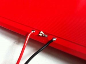
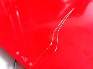
Today how to assemble the MK2 Heatbed-Plate(HBP): First solder the SMD-Parts on the plate. We used:
- 2x SMD-805 leds with blue color
- 1x SMD-805 resistor 490 ohm
If you solder by hand, be quick. SMD-parts dont like to get heated up to much. After soldering the parts on, take two cables with different color. Black and red for example and make sure that the cable has a cross-section (thickness) of min. 0,75mm². Attention please! The HBP takes up to 12A and thin cable will meld in short time.
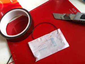
Great after soldering all parts and cables on we will take a heat thermistor which detectes the temperature of the HBP. Beside you need a roll of kapton to isolate everything. A cuttingknife. Heatthermistor and a short cable 0,15mm² for example.
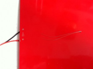
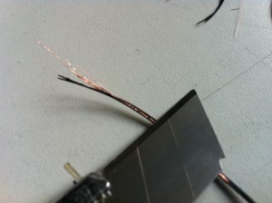
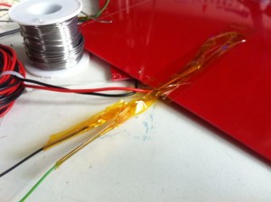
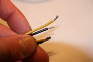
On the right picture you could see that the heatthermistor-legs arent long enough to reach the outside of the plate. We will cut of the 0.15mm² cable to get some thin cables and make the thermistorlegs a bit longer.
Left: How to get a small thin cable out of a bigger one. Right: the thermistor with longer legs. After isloate each leg of the thermistor, mount a isolated cable on the outside of the bed. This guarantee that you have a really flat surface.
Now I tape some kapton around all cables. I love kapton. Its sticks really well, is perfect for electric components, temperature resistent and easy to remove. So if anything broke i can fix it fast.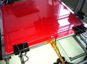
Now lets come to wire up the heatbed to the printer-electric. After a lot of testing. Smoking boards and messauring temperature over hours, we decide that there are two options how you can power up the heatbed.
Any other options we tested are NOT MADE FOR CONTINUOUS or SAVE use!! (be aware this is DIY)
First solution (using a SSD-Relay – best choice):
Things you need:
SSD-Relay – Input 3-32VDC – Output 24-240VAC up to 20A(will work with 12V)
ATX-powersupply – min. 12v up 12A
some thick cables (1mm² – bigger is better)
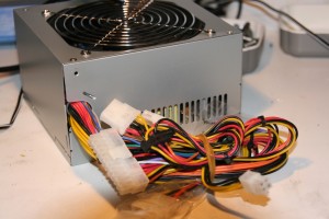
Lets start with the ATX powersupply. In general its wired up to a computer and if you press the ON button of your computer. The powersupply starts. We have no computer so we make a little trick.
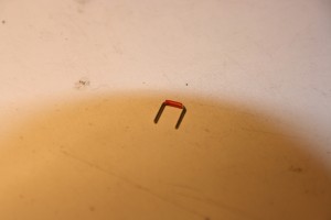
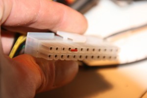
We have to bridge the contacts that are responsible for the startup of the ATX powersupply. Use the contacts 04 and 05 and bridge them with a cable.
Now the ATX powersupply will start immediately.
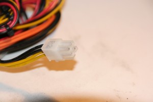
Next we need some open cables from the supply to wire them up with the heatbed. Search for a 4pin connector. Most times black and yellow.
Normally it goes to the CPU of your motherboard.
So you there must be enough power to heat up the heatbed.
Cut of the 4pin connector, we need to of the cables.. The others can be isolated or used to power up the printer-electric.
(i prefere to use 2x powersupplys. 1x for the printerelectric and 1x for the heatbed – seperate big electric components is used in the industry to avoid faults )
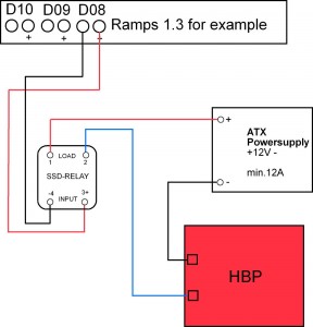
Now take the two cables from the power supply and the two of the HBP supply and mount them on the SSD-Relay.
1 – 12v+ Powersupply
2 – HBP (one cable)
the two other cables, ground of the powersupply and the HBP cable no.2 have to connected together. So solder and isolate them for example or use a connector.
Now we have to connect the SSD RELAY input with the ramps heatbed-output.
(Cool the SSD-relay with a fan, it will heat up!)
Make sure everything is wired correct.Test it!
Secound solution (using a BIG MOSFET on your electric – a bit more advanced):
coming up soon….
IMORTANT NOTICE:
All components of a selfbuild heatbed have to been choosen right.
Use thick cables! Cool down all switches (SSD or Mostfet) because they getting hot while driving so much energy.
Use it carefull to have fun with printing.

